
 |
This project was born out of a need for a flexible, low
cost Data logger. looking around at the market the choice seemed to be between low cost devices that typically were limited to 0-10V or 0-5V inputs with no built in facilities for anything else. which means that in order to use them you first needed to build signal conditioning circuitry. While this may seem simple enough it can involve quite a bit of work and/or expense which would quickly eat in to any savings made. The other end of the market were high end Data-loggers offering 12 bits or more sample size |
My requirements for a Data logger were:
| 10 bit | 10 bits gives me a span of 1023 which is more than adequate for
most measurement requirements. Most modern Data loggers are at least 10 bit. |
| Statistical data | None of the lower cost data loggers I looked at could provide any statistical information - merely the last recorded sample. |
| Flexible inputs | None of the lower cost data loggers I looked at provide any facilities for input signal conditioning. The one presented here uses a plug in conditioning board which in turn has facilities for plug in modules to 'configure' the input. |
| No special software needed | Software is needed to talk to the unit, however as this is a simple terminal program then either Hyper term (which comes with Windows), or Terra term (downloadable for free from the internet) can be used or there are any one of a number of other programs available. |
| CSV compatible | So data can be graphed and analysed using a regular spreadsheet the device presented here outputs data in a CSV format. |
I need to point out that this device is not a true data-logger as (in its current form) it has minimal memory and is instead intended to be connected to a regular computer via a serial port. This was to help keep costs down, as while SD memory cards are cheap, interfacing with them is still fairly complex and an old secondhand computer (even an old laptop) can often be purchased or acquired for much less than the components needed to interface to an SD card.
Future development however will include a Static RAM card and a battery backed Real Time clock
A PC is required to analyse the data anyway and since a stand alone unit may be useful in many cases leaving a PC connected would not be a major problem anyway.
I decided on a Serial port over a USB port for several reasons. The first was that it simplified development significantly, Secondly it keeps the cost down - especially as I can purchase a USB to serial adapter for less than I can buy a USB interface chip. Thirdly I expect this project to be connected to an older (cheaper) computer and while most older computers have serial ports they may not all have USB ports.
Additionally I have provided facilities on the PCB to install an RS485 interface instead of RS232 so that the Acquisition unit may be located a distance from the Computer. the RS485 interface however will require a special interface adapter for the PC and I have not yet developed this.
 |
 |
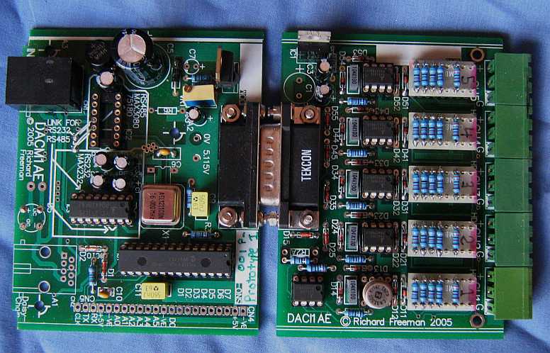
The circuit itself is very straightforward - a PIC16F876
embedded controller does most of the work this chip has a 5 channel 10 bit
ADC built in to it, a Serial interface and enough memory to look after
sampling and Averaging. I decided to use an External Oscillator (at a small increase in cost) instead of just a crystal as this also allows the option of using a temperature compensated Oscillator if more precise sample times are an issue. The MAX232 translates the TTL levels from the serial port into RS232. I have used a variable regulator which allows the Supply rail to be trimmed to 5.115V since |
The connector marked X2 is for future expansion options such as a battery backed RTC, Memory for Data logging and a control Relay for switching on external devices when Logging begins.
Power and Serial port connect via an RJ45 connector (although the current version also has facilities for a Separate power supply) and this power supply can be between 10 and 27 volts.
there are a number of options available for powering this System:
it can be powered from a local double insulated plug pack (either AC or DC output) although please note that the modern 'MEBs' compliant so called double insulated switchmode plug packs have serious potential safety issues.
It is powered via the RJ45 cable either from a floating or double insulated supply on pins 1+2 and 7+8
or, it can be powered from a supply common to the monitoring PC with ground on 3+6 and power on either 1+2 or 7+8 of the RJ45.
Note that the diode D4 maintains the Digital system ground at around 0.56V above the analogue and power supply ground. This is done in order to allow the input op-amps to be able to drive the analogue inputs to true 0, this also effectively means that the RS232 signals will be half a volt high but RS232 is designed to cope with small offsets like this and it has not been found to be an issue in practise
Much of the flexibility of this system comes from the input board
 |
The input board uses CA3130 Op-amps for buffering and signal
conditioning. These were chosen for their Low voltage working, high input impedance and ability to drive their outputs to within a fraction of a volt of their supply rail. The supply rail for the CA3130 is Regulated at 9V by a 7909 and thanks to D4 is roughly 560mV below the supply for the ADC/PIC16F876. this allows the Op-Amps to drive to the ADC's 0V rail. A sixth 3130 can be used to buffer a reference voltage from either a voltage divider or diode. |
 |
Dx1, 2, 3, 4 are for overvoltage protection for the op-amps these are BAS45 low leakage diodes to minimise their loading on the Signal being amplified.
Rx1-4 set the gain of the Op-amps.
Rx5 can be used to power any Sensor/Transducer while Rx6 can be used for single ended measurements and Rx7 can be used for any current measurement. The resistors Rx1 - 7 can be mounted on a DIP carrier so that different configurations and gain can be changed easily.
Rx8 and Dx5 provide protection for the ADC in the event that the output of the Op-amp gets driven above the 5.115V supply rail
The following example shows how the input module could be set up as an interface for the popular Lm335 temperature sensor
 |
R2B and R3 sets the reference Voltage at 2.2V setting the lower temperature limit at -53C R14A is set up to subtract this reference voltage from the measured signal.
R13,14,11 and 12 set the gain at 2.5 making the output from the buffer 25mV per degree Kelvin or 0.2 degrees C resolution.
If you wish to get a feel for how the DACQ operates the user manual may be found here
Full kit is $40 (Australian) and includes:
PCBs for both the Data Acquisition module and an Input board
Pre-programmed 16F876
5 x DIP headers
Assembly and operation/programming instructions
Purchase
Unfortunately the cost of
Electronic components and shipping from Australia is not cheap, so I am selling these as
short form kits (PCB, Instructions and any programmed parts) rather than complete
kits.
At the
moment I am selling these through Ebay which for this project includes:
PCB and Assembly
instructions
Email if you require any more info....
Copyright © 2011 Australian
Technical Production
Services