
|
| Home | About Us | Contact Us | DIY Projects | Tutorials |Pictures |Retro Computing | The Luddite |
| Page 2 | PDF Version | |
Covering Firmware version 1.1B (Production)
Contents
Interfacing to the
DACM
Serial Interface.
Power supply.
Signal input
conditioning.
Calibration.
Capturing Data from the
DACM.
Understanding the Day and Time.
Command Reference.
Configuration
(Set) Commands.
Set Beginning time.
Set Channel
options.
Set Inputs.
Set
Limit
Set
Off
Set
Pause.
Set
Pause Off
Set Sample
interval
Set
Time.
Operation
Commands.
Run.
Start Run.
Display
Channel
Display Settings.
Display
Time.
Display Version.
Development 0.02D /
Production Release 1.1A - Initial Release
No known bugs at
03/12/2008
The DACM uses a Serial port (running at 19K2 8, n, 1) to communicate with the host system. Depending on the option selected this may be either RS485 or RS232. I elected to use RJ45 connectors as Cat 5 cable is inexpensive and readily available.
RS485 (currently untested) should give a range of 40 meters over Cat 5 cable however, this is subject to a number of variables and you will need to verify performance for yourself.
RS232 should provide adequate performance up to 10 meters.
The DACM is designed to run off +12V which can be provided locally via the power connector or using pins 1+2 and 7+8 on the RJ45. The power supply is internally regulated by the DACM and it can handle up to 24V without damage, however the supply should not drop below 11 Volts as this may cause inaccurate readings.
The power goes through a bridge rectifier this means that the Ground connectors on the inputs may be 0.6V above the ground on the power supply, also the DACM uses negative ground. Connection to positively grounded power supply may cause damage to the DACM
One of the features that makes
the DACM stand out from the other low cost alternatives, is the signal input
conditioning board which can be set up to deal with many different input
signals. While the DACM can be used without the conditioning board it is
recommended that you use it as the input board also contains the over voltage
protection.
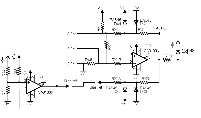 |
ICx1 (x is the channel number) is set up as a differential amplifier where Resistors Rx1, Rx2, Rx3 and Rx4 (A or B) set the gain where gain = Rx1/Rx2 (Rx1=Rx3 and Rx2=Rx4) Rx7 can be used for current measurement or as part of a voltage divider (in conjunction with external resistors in series with the input) and Rx5 can be used to provide power to sensors/Transducers (if required).
For example the following circuit may be used with an LM135, 335 or 235 temperature sensor.
R15 provides Power for the LM335.
R11, 12, 13 and 14A set the gain to 2.5 this means that with the LM335's 10mV
per 1C is amplified to 25mV and with the DACM reading 5mV per step gives us a
resolution of 0.2C.
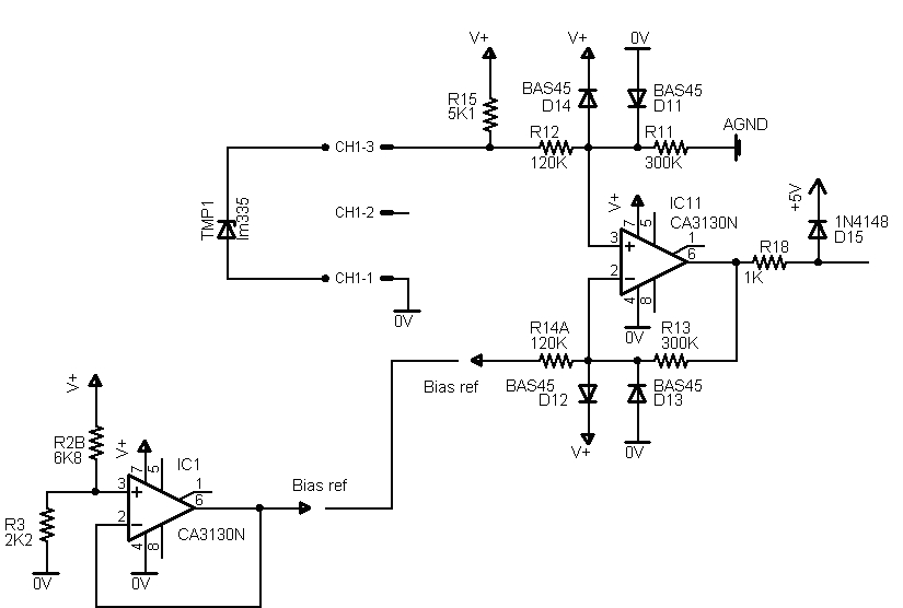 |
The use of R14A means that the output from the op amp will be dependant on the input voltage minus the Bias reference voltage which in this case this sets the lowest reading that DACM can take this is set to 2.2V (220K) or -53C so with this circuit we can use the DACM and an LM335 to measure from -53C to +151.6C with 0.2C resolution. Note that only the LM135 handles -50C to 150C.
Calibration may be achieved by adjusting the multi-turn trim pot on the main board until the 5V rail is at 5.115V - this provides the reference voltage for the internal ADC and 5.115V means that an input voltage of 5V will equate to a reading of 1000 or a resolution of 5mV.
Alternatively if you have an accurate low voltage supply (less than 5V) adjust the Trimpot until you are getting a reading from the DACM corresponding to Vin/5mV
DACM uses a serial port to interface with the host machine although a USB interface was considered it would have added to the cost of the project significantly and Serial to USB adapters can be purchased for less than it would have cost to add USB to this project. Also using a Serial interface means that many if not most older machines can be used to log data from the DACM rather than tying up a newer machine.
Rather than depending on dedicated software to run on the host machine this project has been developed to use readily available terminal software - although Hyperterm (which is supplied free with windows) may be used, I recommend you download Tera term which is available free off the internet as it has a number of advantages over Hyperterm Particularly when it comes to logging data from the DACM.
The DACM sends data to the Serial
port in a CSV (Comma Separated Variable) format which can be readily understood
by any Spreadsheet program - including Excel, Lotus etc.
In order to capture the data from
the DACM use the Log function on the Terminal program - in Tera term this is
under File/Log on Hyper term this is under Transfer/Capture text. If you set the
Pause option on the DACM (see command reference below) then you have 10 seconds
after entering run to start logging the file - with Hyperterm this means that
you have ten seconds to select Transfer/Capture text then select a directory and
enter a file name.
With Tera Term however, as soon as you have selected
File/Log then Tera Term will start buffering data from that point on and this
allows you plenty of time to select a Directory and enter a file
name.
Since the data is stored as a CSV I suggest you use the extension
.csv when specifying the log file name.
The DACM does not contain a fully fledged Real time clock so it does not keep track of the Date, instead it counts days using an 8 bit Register. As a result the Day is an integer between 0 and 255 if the DACM is logging data for more than 255 Days the Day register rolls over and restarts from 0.
There is no internal battery so for critical logging applications a battery backed power supply will be required so that logging will not be interrupted, this means though, that if the DACM loses power, the Time and Day reset back to 0,00:00:00 on power up.
The day and Time can be set to a
predetermined value which is then used as the Day and Time stamp by the DACM
when the run command is used. Alternatively if the start command is used the
time and Day registers are reset to zero when logging is started so that the
time and Day stamp is relative to the start time.
The accuracy of the Day/Time
reference is going to be as good as the Oscillator module you choose. Typical
crystal oscillators have an accuracy of around 100 parts per million - this
translates to roughly 8.6 Seconds per day. However if the oscillator modules are
maintained at 25C they will generally be much more accurate than this.
Wristwatches maintain a higher accuracy than this because the crystals they use are cut to be accurate at slightly under body temperature as they are designed to be worn and heated by the human body.
Temperature Compensated Crystal Oscillators (TCXO's) are available which claim an accuracy of better than 20 PPM or 1.728 Seconds per day - these however cost somewhat more and I suspect that for most applications <100PPM will be adequate.
SB ddd,hh:mm:ss
Sets the Time at which the DACM will start logging Data
e.g.
SB 16,12:00:00 will start logging data on Day 16 at 12:00:00
NOTE that the DACM will NOT start logging data after this command has been entered unless the Run command has also been entered.
SC chlac
Sets the Data to be logged from each channel -
Options for this command are:
H - High, this logs the highest reading in the Sample periode.g.
SC 1HL,2AC,3H,4L will set up Channel 1 to log High and Low readings, Channel 2 will log Average and last reading, channel 3 will log High readings, channel 4 will log low readings and channel 5 is not configured in this instance.
Note the channels will not be read unless they are also enabled
SI x,x,x,x,x
This command enables the inputs to be read
e.g.
SI 1,2,3
Enables channels 1, 2 and 3, while channels 4 and 5 remain disabled (unless previously enabled).
Note that this command Enables channels only, it does not disable any channels that may have previously been enabled
SL xxxxx
This command sets a limit to the number of samples taken - this limit can be between 1 and 65535 (note that Excel has trouble when dealing with more than 32768 lines)
When the required number of samples has been taken the DACM will halt
e.g.
SL 500
Limits the number of samples taken to 500
SO x,x,x,x,x
This command disables inputs so they are not read
e.g.
SO 2,3,4,5
Disables channels 2, 3, 4 and 5 channel 1 is not disabled in this example and remains as it was before this command.
Note that this command only disables channels it does not enable any channels not included in the command
SP
This sets a 10 Second pause between when the run command is entered and when the DACM starts logging data. To turn the Pause off enter SP0
e.g.
SP
Enables a 10 Second Pause after run has been entered before the DACM starts logging data
SP0
Turns off the 10 Second pause between entering run and logging data - note that the 0 is the number zero not the letter O
e.g.
SP0
Disables the 10 second pause between typing run and the DACM logging data
SS hh:mm:ss
This command sets the time for
the sample interval (that is the time between readings) this ranges from 1
second (00:00:01) to 24 Hours 00 minutes 00 seconds (24:00:0) Average,
will be the average of readings taken over this interval.
Other
options:
SS
F
-note rev 1B only
Sets the Sample time to
Fast - this means that the DACM will provide readings as fast as teh serial port
will let it - Note that Sample times will vary under this otion according to the
time taken for the Data to be transmitted.
SS
C
-note rev 1B only
Sets the Sample time to
fast/Controlled this will provide readings every 20mS
Note that in either
Fast or fast/Cotrolled mode you can only take either Current or Average readings
- if both options are set the DACM will default to Average.
e.g.
SS 12:00:00
Sets the sample interval for 12 Hours
ST ddd,hh,mm,ss
This Command sets the Day and Time for the internal clock Time is in 24 Hour format and the Day is an integer between 0 and 255
e.g.
ST 127,19:30:00
Sets the Time as Day 127 1930 Hours (i.e. 7:30:00 Pm)
Run
Starts the DACM logging data. Either at a prearranged time, if the SB command was used, after a 10 Second pause if SP was entered or immediately if neither of these two settings were used. Day and Time stamps are not affected by this command.
To stop logging data press the Escape key
Start
Starts logging data immediately (unless SP has been entered in which case it will start after a 10 second pause) Start will clear the Day and Time registers when it starts so that all day and time stamps are relative to when logging was started.
To stop logging data press the Escape key
DC
-note rev 1B only
Shows Channel settings
DS
-note rev 1B only
Shows current settings -
DT
Shows the current Day and Time.
Note this is not currently a live display.
DV
Shows the firmware revision.
Copyright © 2009 Australian Technical Production Services