
Description
There are plenty of Passive
crossover kits and PCBs around but this one also addresses a problem that many do not
touch, Tweeter protection.
Many of you will have noticed that tweeter Failures are not uncommon particularly in
Sound reinforcement systems.
I have heard many theories attempting to explain this involving clipping and
distortion, but really the reason is very simple:
Tweeters, particularly horn loaded compression drivers are very sensitive, often 6 to
12dB more so than the lower frequency drivers.
High frequency power of 'normal music' expected from the Tweeter is often as low
as 25% of the total acoustic power.
What all this means is that a tweeter only needs to have a fraction of the power handling
of the speaker system as a whole and 50 Watt tweeters in 500W speakers are not entirely
unheard of.
Now when everything is working as it should this is fine, but when
something starts feeding back, and your Amplifier starts trying to deliver full
power to your Tweeter, then its future life expectancy is often measurable in
fractions of a second....
Having had a number of Tweeter failures I decided it was time to
investigate protection.
The speakers I had on hand with blown tweeters had been protected with poly switches yet
had still failed.
I had heard that selecting the best poly switch was always a balance between adequate
protection and nuisance tripping so I ran some tests on three Poly switches: RXE110
(Rated at 2.2A or 38.72W @ 8 Ohms) RXE090 (Rated at 1.8A or 25.9W @ 8 Ohms) and RXE075
(Rated at 1.5A or 18W @ 8 ohms).
To
test the response times of the poly switches I used the following test
rig:
 |
I used a Tektronix TDS210 as the oscilloscope set as single shot, at 1 second per division and a dummy load of 4 Ohms (the dummy load has a 2:1 output to the oscilloscope).
With this setup I could measure with a reasonable degree of accuracy, how long the poly switch took to open.
For the first round of tests I ran 4.1 Amps through the poly switch and measured how long the poly switch took to open:
Despite this being almost twice the trip current of the RXE110, it took almost 4 Seconds to open:
 |
The RXE090 took almost 3 Seconds to open and even the RXE075 took 2.5 Seconds to open.
Having tested several Tweeters to Destruction (by no means
an exhaustive test as Tweeters are expensive, but more to get an indication of how
long a tweeter could last) I had found that most nominal 50Watt tweeters would be
lucky indeed to last 2 seconds at 128 Watts.
I also found that many of the cheaper '50 Watt' tweeters were in fact lucky to
survive several seconds at full power, although to give credit where credit is due the
two more expensive tweeters I tested did handle rated power for several hours - despite
being mounted inside an insulated wooden box (the test got rather loud otherwise).
The conclusion I reached was, that while Poly
switches are better than nothing, they are barely adequate as Speaker
protection.
Lightbulbs likewise proved to be problematic - either getting consistent lightbulbs or
lightbulbs that provided adequate protection without false tripping or
failure.
What I needed, was protection that tripped at a preset
point, allowed a slight (but not significant delay) before tripping (to avoid
tripping on otherwise harmless signals), preferably a circuit that reset itself
when the danger had passed and just to add to the challenge a circuit that required
no external power....
This is the circuit I came up with:
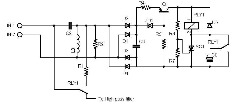 |
C9 and L3 act as a high pass filter, while
R9 provides a constant/predictable load for the filter.
D1 to D4 are UF4001 high speed diodes acting as a full wave rectifier and
C6 - 1uF (May be varied to suit application) acts as a Filter/Delay.
R6 (Set as required) and R7 (560 Ohm) act as a voltage
divider to trigger for the SCR SC1, and determine the voltage at which
the protector trips. R6 may be calculated by R6= (Tv-0.56)*1000 where Tv is the
trip Voltage.
R1 allows the Input filter to be bypassed
if/when the protection is triggered this would mean that protection remains active
until it is reset by a compete absence of signal - I have not used this
option yet but I would suggest R1 of around 39 Ohms (if used).
C8 (10uF) ensures that the SCR is reset when the Relay drops
out.
Finally Q1(MJE340), R4 (85 Ohm), ZD1 (3V3) and R5 act
as a current limit to stop the Relay burning out when protection is
active.
RLY1 is a Relay with a 400 Ohm coil and R9 is set
at 150 Ohms, This sort of load should be insgnificant when compared to typical 4, 8
or even 16 ohm speaker systems.
While I did
experiment with alternative methods of resetting the SCR that did not involve an
extra pair of Relay contacts, the Relay I ended up going with only cost $1
more than the SPST Relay and has 5 Amp contacts instead of 3
Amps.
The reason for having a high pass filter in front of
this circuit rather than installing this circuit after the existing high pass
filter in the crossover is that if the tweeter alone is disconnected, then in the
case of a second order crossover, the high pass filter for the tweeter will act as
a series resonant circuit and this may cause stability issues for some
Amplifiers.
Of course this is a Crossover, so by the time I add all the other components for a second
order crossover we get:
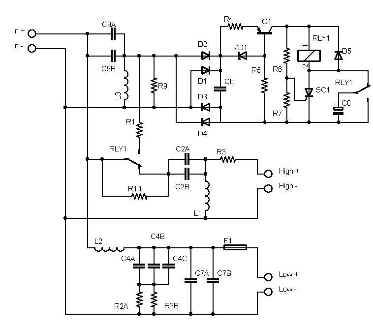 |
L2 and C7 are the low pass filter for the woofer while C4 and R2 provide impedance correction for the woofer.
Woofers are largely inductive by the time you get to their crossover point and may have an impedance of 40 Ohms or more, as a result simple 2nd order crossovers can end up providing far less than the expected 12dB per octave rolloff.
This may or may not be an issue, but if it is, then impedance correction will help fix this
F1 only provides 'Line of last resort' protection for the woofer - by far the majority of failures I see are of the tweeters and by the time you fry a woofer things have gone horribly wrong and a Relay that can handle the sorts of currents involved is going to be quite substantial.
If I am to be honest though, the fuse was really added as the PCB needed a link and I figured an appropriately sized fuse was unlikely to cause any harm.
Calculations for all these component Values are included along with worksheets in the Instructions for this project (PDF)
Note that you need not add all of these components if you wish (not even the tweeter protection if you do not want - although I suspect you could get a cheaper PCB if you did not want this option).
Purchase
Unfortunately the cost of
Electronic components and shipping from Australia is not cheap, so I am selling these as
short form kits (PCB, Instructions and any programmed parts) rather than complete
kits.
At the
moment I am selling these through Ebay which for this project includes:
PCB and Assembly
instructions
Email if you require any more info....
Copyright © 2011 Australian
Technical Production Services